The PLATO Payload comprises the cameras including focal planes and related electronics as well as the on-board data processing system. The PLATO Payload (provided by the PLATO Mission Consortium) plus the optical bench on which the cameras are mounted (provided by ESA), constitute the PLATO Payload Module.
Driven by science requirements calling for a very large field of view (FoV), coupled with a sensitivity of a 1 m-class telescope, the PLATO instrument concept is based on a multi-telescope approach (cf. the rational beyond the segmentation of the optic design), involving a set of 24 Normal Cameras working at a cadence of 25 sec and monitoring stars fainter than mV = 8, plus 2 Fast Cameras working at a cadence of 2.5 sec, and observing stars in the magnitude range 4 to 8.
A camera includes a Telescope Optical Unit (TOU), a Focal Plane Assembly (FPA), which supports four CCD detectors, the Front End Electronics (FEE) box, the FEE Support Structure (FSS), and related thermal equipment. The TOUs are based on a fully dioptric telescope including 6 lenses.
Each camera is equipped with its own, passively cooled FPA, comprised of 4 CCDs with 4510 × 4510 pixels each, working in full frame mode for the “normal” cameras, and in frame transfer mode for the “fast” cameras. This results in 1037 deg2effective field-of-view for the “normal” cameras and 619 deg2 field of view for each of the two “fast” cameras.
Besides providing star brightness measurements for bright stars, the “fast” cameras also work as fine guidance sensors for the attitude control system of the Spacecraft. In addition they allow measurements of stars in two spectral bands. For this purpose one of the “fast” cameras is equipped with a blue, the other one with a red bandpass filter.
The 24 “normal” cameras are arranged in 4 groups of 6 cameras. All 6 cameras of each group have exactly the same field-of-view. However, the lines of sight of the four groups are offset by an angle of 9.2° from the PLM +Z axis.
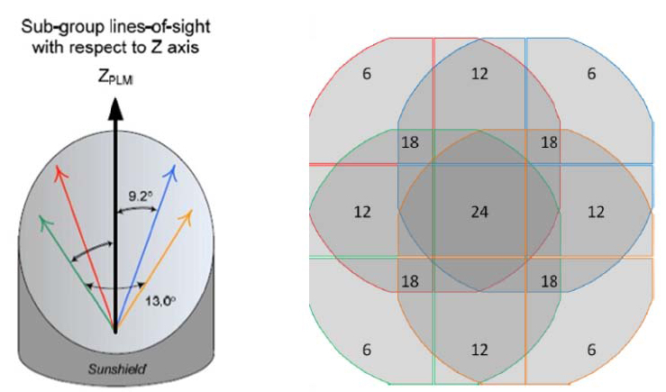
The overlapping line-of-sight concept (left) and the resulting field-of-view configuration (right).
This particular configuration allows PLATO to survey a total field of about 2232 deg2 per pointing, with various parts of the field monitored by 24, 18, 12 or 6 cameras. This strategy optimises both the number of targets observed at a given noise level and their brightness. The satellite will be rotated around the mean line of sight by 90° every 3 months, resulting in a continuous survey of exactly the same region of the sky.
At the beginning of each pointing full images will be transferred to ground to serve deriving the PSF at each target position. To reduce the high data volume produced on-board during operation, each assigned target star will be allocated a CCD window around it from which all the pixel values will be gathered, forming a small image called an “imagette”. The size of this window is typically 636 pixels (939 pixels for the fast cameras), large enough to contain the whole image of the target star. These imagettes will either be sent as raw data to ground or processed on-board to get centroids and light curves to further reduce the telemetry data volume. The raw imagettes are used on ground to derive the PSF at different positions of the detector, a step which is needed to verify the quality of the photometric and centroiding data. For calibration purposes and to define imagette positions after re-pointings, also full frame images will be transmitted to ground.
There is one Data Processing Unit (DPU) per two “normal” cameras performing the basic photometric tasks and delivering a set of light curves, centroid curves and imagettes to a central Instrument Control Unit (ICU), which stacks and compresses the data, then transmits them to the SVM for downlink. Data from all individual cameras are read-out every 25s and transmitted to the ground, where final instrumental corrections, and e.g. jitter correction, are performed. The DPUs of the fast cameras will also deliver a pointing/attitude error signal to the AOCS, at a cadence of 2.5s.
Each DPU of the “normal” cameras (N-DPU) is associated with two FEEs. They are grouped together in a Main Electronics Unit (MEU). There are 2 MEUs containing 14 N-DPUs for the 28 normal cameras, each one including its own power supply electronics.
The fast DPUs (F-DPU) are functionally associated to the fast FEE. There are 2 F-DPUs, one per fast FEE, grouped in one box called Fast Electronics Unit (FEU), also including its power supply.

The PLATO on-board data treatment architecture.
Cameras receive their power from the Ancillary Electronics Units (AEUs), one AEU per fourteen “normal” cameras and one AEU for both “fast” cameras. The AEUs also provide synchronisation signals for data acquisition and cameras thermal control. The payload is controlled by two ICUs used in cold redundancy. The two ICUs are grouped in a single box with their own power supply.
In addition, the instrument includes on-board software, operating on the DPUs and ICUs, which can be modified during the flight.
More information on the Payload are given below.
Single Cameras
| Characteristics | Value | Comments |
| Optics | Full refractive design with 6 lenses and 1 entrance window | Axisymmetric design |
| Optics spectral range | 500 – 1000 nm | |
| Pupil diameter | 120.0 mm | For one telescope |
| Camera focal plane layout | 4 CCDs in a square | |
| Normal camera detectors | Full frame CCDs
451034510 light sensitive, |
e2v CCD 270 |
| Fast camera detectors | Frame transfer CCDs
451032255 |
e2v CCD 270 |
| Normal camera field of view | ~ 1037 deg²
~ circular, diameter 37.8° |
For each telescope |
| Fast camera field of view | ~ 619 deg² | For each telescope. Only 50% of the focal plane light sensitive due to selection of frame transfer CCDs |
| Plate scale | 15.0 arcsec / px | For both normal and fast telescope |
| PSF surface | Always included within 9 px | |
| CCD temperature | < – 65°C | By passive cooling |
| Read-out frequency | 3 Mpx/s | |
| Normal camera CCD
cycle period |
25.0 s fixed | |
| Fast camera CCD cycle period | 2.5 s fixed | |
| Normal camera exposure time | ~ 22.0 s fixed | + a shorter exposure time for on-ground, at room temperature, tests |
| Fast camera exposure time | ~ 2.3 s fixed |
Combined Cameras
| Characteristics | Value | Comments |
| Number of telescopes | 24 Normal + 2 Fast | |
| Field-of-view | Overlapping FoV of 2232 deg² |
|
| Power | ~ 820 W | |
| Payload Mass | 533 kg | |
| Electronics |
|
|
